
Icon of the Module
Some of the below described features are not available in the open-source part of the MITK-3M3-Application.
Available sections:
The Segmentation perspective allows you to create segmentations of anatomical and pathological structures in medical images of the human body. The perspective groups a number of tools for
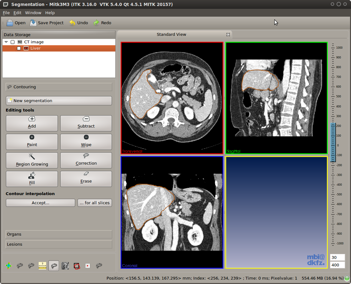
Segmentation perspective consisting of the Data Manager view and the Segmentation view
If you wonder what segmentations are good for, we shortly revisit the concept of a segmentation here. A CT or MR image is made up of volume of physical measurements (volume elements are called voxels). In CT images, for example, the gray value of each voxel corresponds to the mass absorbtion coefficient for X-rays in this voxel, which is similar in many parts of the human body. The gray value does not contain any further information, so the computer does not know whether a given voxel is part of the body or the background, nor can it tell a brain from a liver. However, the distinction between a foreground and a background structure is required when
Creating this distinction between foreground and background is called segmentation. The Segmentation perspective of MITKApp uses a voxel based approach to segmentation, i.e. each voxel of an image must be completely assigned to either foreground or background. This is in contrast to some other applications which might use an approach based on contours, where the border of a structure might cut a voxel into two parts.
The remainder of this document will summarize the features of the Segmentation perspective and how they are used.
The Segmentation perspective makes a number of assumptions. To know what this module can be used for, it will help you to know that:
The Segmentation perspective makes use of the Data Manager view to give you an overview of all images and segmentations.

Data Manager is used for selection of the current segmentation. The reference image is selected in the drop down box of the control area.
To select the reference image (e.g. the original CT/MR image) use the drop down box in the control area of the Segmentation view. The segmentation image that has been selected in the Data Manager is displayed below the drop down box. If no segmentation image exists or none is selected create a new segmentation image by using the "New segmentation" button. Some items of the graphical user interface might be disabled when no image is selected. In any case the application will give you hints if a selection is needed.
With manual contouring you define which voxels are part of the segmentation and which are not. This allows you to create segmentations of any structeres that you may find in an image, even if they are not part of the human body. You might also use manual contouring to correct segmentations that result from sub-optimal automatic methods. The drawback of manual contouring is that you might need to define contours on many 2D slices. However, this is moderated by the interpolation feature, which will make suggestions for a segmentation.
Unless you want to edit existing segmentations, you have to create a new, empty segmentation before you can edit it. To do so, click the "New manual segmentation" button. Input fields will appear where you can choose a name for the new segmentation and a color for its display. Click the checkmark button to confirm or the X button to cancel the new segmentation. Notice that the input field suggests names once you start typing and that it also suggests colors for known organ names. If you use names that are not yet known to the application, it will automatically remember these and consider them the next time you create a new segmentation.
Once you created a new segmentation, you can notice a new item with the "binary mask" icon in the Data Manager tree view. This item is automatically selected for you, so that you can start editing the new segmentation right away.
As you might want to have segmentations of multiple structures in a single patient image, the application needs to know which of them to use for editing. You select a segmenation by clicking it in the tree view of Data Manager. Note that usually segmentations are displayed as sub-items of "their" patient image. In the rare case where you need to edit a segmentation that is not displayed as a a sub-item, you can click both the original image AND the segmentation while holding down CTRL on the keyboard.
When a selection is made, the Segmentation view will hide all but the selected segmentation and the corresponding original image. When there are multiple segmentations, the unselected ones will remain in Data Manager, you can make them visible at any time by selecting them. If you want to see all segmenations at the same time, just clear the selection by clicking outside all the tree items in Data Manager.
If you are familiar with MITKApp, you know that clicking and moving the mouse in any of the 2D render windows will move around the crosshair that defines what part of the image is displayed. This behavior is disabled while any of the manual segmentation tools are active -- otherwise you might have a hard time concentrating on the contour you are drawing.
To start using one of the editing tools, click its button the the displayed toolbox. The selected editing tool will be active and its corresponding button will stay pressed until you click the button again. Selecting a different tool also deactivates the previous one.
If you have to delineate a lot of images, you should try using shortcuts to switch tools. Just hit the first letter of each tool to activate it (A for Add, S for Subtract, etc.).
All of the editing tools work by the same principle: you press the mouse (left button) anywhere in a 2D window (any of the orientations transversal, sagittal, or frontal), move the mouse while holding the mouse button and release to finish the editing action. All tools work on the original slices of the patient image, i.e. with some rotated/tilted MR image volumes you need to perform a "reinit" option in Data Manger before you are able to use editing tools.
Multi-step undo and redo is fully supported by all editing tools. Use the application-wide undo button in the toolbar to revert erroneous actions.
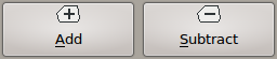
Add and Subtract tools
Use the left mouse button to draw a closed contour. When releasing the mouse button, the contour will be added (Add tool) to or removed from (Subtract tool) the current segmentation. Hold down the CTRL key to invert the operation (this will switch tools temporarily to allow you quick corrections).
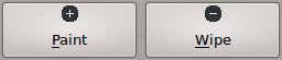
Paint and Wipe tools
Use the slider below the toolbox to change the radius of these round paintbrush tools. Move the mouse in any 2D window and press the left button to draw or erase pixels. As the Add/Subtract tools, holding CTRL while drawing will invert the current tool's behavior.
Region Growing tool
Click at one point in a 2D slice widget to add an image region by the region growing tool to the segmentation. Moving up the cursor while holding the left mouse button widens the range for the included grey values, moving it down narrows it. When working on an image with a high range of grey values, the selection range can be influenced more strongly by moving the cursor at higher velocity.
Region Growing selects all pixels around the mouse cursor that have a similar gray value as the pixel below the mouse cursor. This enables you to quickly create segmentations of structures that have a good contrast to surrounding tissue, e.g. the lungs. The tool will select more or less pixels (corresponding to a changing gray value interval width) when you move the mouse up or down while holding down the left mouse button.
A common issue with region growing is so called "leakage", which happens when the structure of interest is connected to other pixels of similar gray values through a narrow "bridge" at the border of the structure. The Region Growing tool comes with "leakage detection/removal" feature. If leakage happens, you can left-click into the leakage region and the tool will try to automatically remove this region (see illustration below).
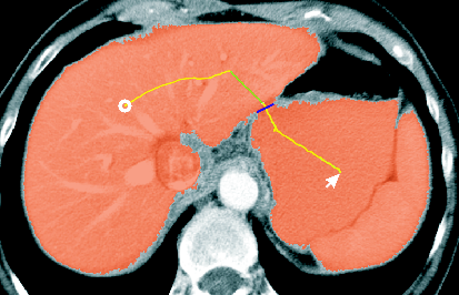
Leakage correction feature of the Region Growing tool
Correction tool
You do not have to draw a closed contour to use the Correction tool and do not need to switch between the Add and Substract tool to perform small corrective changes. The following figure shows the usage of this tool:
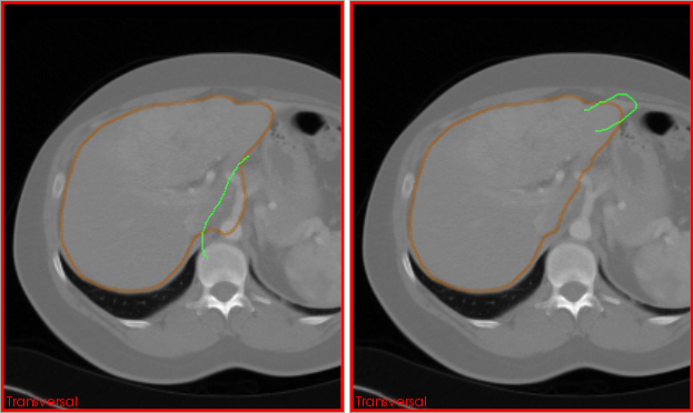
actions of the Correction tool illustrated
Fill tool
Left-click inside a segmentation with holes to completely fill all holes.
Erase tool
This tool removes a connected part of pixels that form a segmentation. You may use it to remove so called islands (see picture) or to clear a whole slice at once (hold CTRL while clicking).
Creating segmentations for modern CT volumes is very time-consuming, because strucutres of interest can easily cover a range of 50 or more slices. The Segmentation view offers a helpful feature for these cases: "Interpolation" creates suggestions for a segmentation whenever you have a slice that
Interpolated suggestions are displayed in a different way than manual segmentations are, until you "accept" them as part of the segmentation. To accept single slices, click the "Accept" button below the toolbox. If you have segmented a whole organ in a every-x-slices way, you may also review the interpolations and then accept all of them at once by clicking "... all slices".
The manual contouring described above is a fallback option that will work for any kind of images and structures of interest. However, manual contouring is very time-consuming and tedious. This is why a major part of image analysis research is working towards automatic segmentation methods. The Segmentation view comprises a number of easy-to-use tools for segmentation of CT images (Liver) and MR image (left ventricle and wall, left and right lung).
On CT image volumes, preferrably with contrast agent in the portal venous phase, the Liver tool will fully automatically analyze and segment the image. All you have to do is to load and select the image, then click the "Liver" button. During the process, which takes a minute or two, you will get visual progress feedback by means of a contour that moves closer and closer to the real liver boundaries.
While liver segmentation is performed fully automatic, the following tools for segmentation of the heart, the lungs, and the hippocampus need a minimum amount of guidance. Click one of the buttons on the "Organ segmentation" page to add an average model of the respective organ to the image. This model can be dragged to the right position by using the left mouse button while holding down the CTRL key. You can also use CTRL+middle mouse button to rotate or CTRL+right mouse button to scale the model.
Before starting the automatic segmentation process by clicking the "Start segmentation" button, try placing the model closely to the organ in the MR image (in most cases, you do not need to rotate or scale the model). During the segmentation process, a green contour that moves closer and closer to the real liver boundaries will provide you visual feedback of the segmentation progress.
The algorithms used for segmentation of the heart and lung are method which need training by a number of example images. They will not work well with other kind of images, so here is a list of the image types that were used for training:
As mentioned in the Heart/Lung section, most of the underlying methods are based on "training". The basic algorithm is versatile and can be applied on all kinds of segmentation problems where the structure of interest is topologically like a sphere (and not like a torus etc.). If you are interested in other organs than offered by the current version of the Segmentation view, please contact our research team.
Lesion segmentation is a little different from organ segmentation, because lesions are not part of the healthy body, sometimes having a diffuse border, and oftenly they are found if varying places all over the body. The tools in this section offer efficient ways to create 3D segmentations of such lesions.
The Segmentation view currently offers supoprt for enlarged lymph nodes.
To segment an enlarged lymph node, find a more or less central slice of it, activate the "Lymph Node" tool and draw a rough contour on the inside of the lymph node. When releaseing the mouse button, a segmentation algorithm is started in a background task. The result will become visible after a couple of seconds, but you do not have to wait for it. If you need to segment several lymph nodes, you can continue to inspect the image right after closing the drawn contour.
If the lymph node segmentation is not to your content, you can select the "Lymph Node Correction" tool and drag parts of the lymph node surface towards the right position (works in 3D, not slice-by-slice). This kind of correction helps in many cases. If nothing else helps, you can still use the pure manual tools as a fallback.
As mentioned in the introduction, segmentations are never an end in themselves. Consequently, the Segmentation view adds a couple of "post-processing" actions to Data Manager. These actions are accessible through the context-menu of segmentations in Data Manager's list view
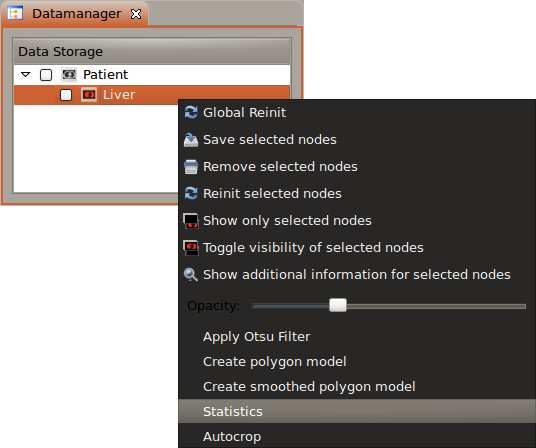
Context menu items for segmentations
You can use the surface masking tool to create binary images from a surface which is used used as a mask on an image. This tast is demonstrated below:
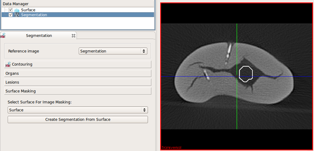
Load an image and a surface. Select the
image and the surface in the corresponding drop-down boyes (both is selected automatically if there is just one image and one surface)
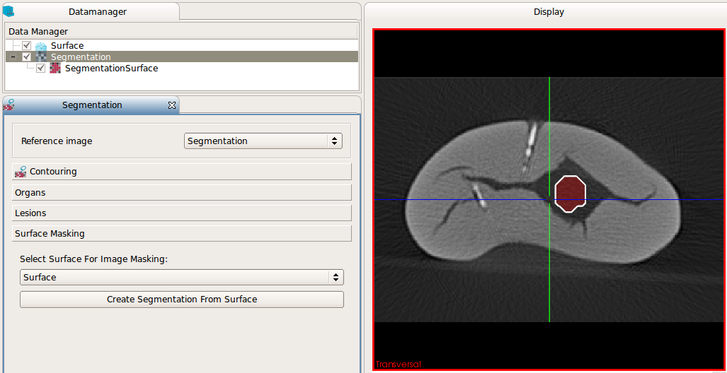
After clicking "Create segmentation from surface" the newly created binary image is inserted in the DataManager and can
be used for further processing
 1.7.2
1.7.2

