This module provides means to diffusion weighted image reconstruction, visualization and quantification. Diffusion tensors are supported as well as different q-ball reconstruction schemes are supported. Q-ball imaging aims at recovering more detailed information about the orientations of fibers from diffusion MRI measurements and, in particular, to resolve the orientations of crossing fibers.
Available sections:
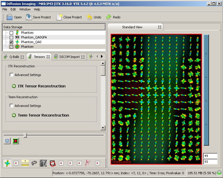
The MITK Diffusion Imaging Module
The tensor reconstruction view allows ITK based tensor reconstruction [3].
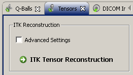
ITK tensor reconstruction
The advanced settings for ITK reconstruction let you configure the number of threads to be used and a manual threshold on the non-diffusion weighted image. All voxels below this threshold will not be reconstructed and left blank.
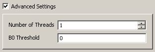
Advanced settings for ITK tensor reconstruction
A few seconds (depending on the image size) after the reconstruction button is hit, a colored image should appear in the main window.
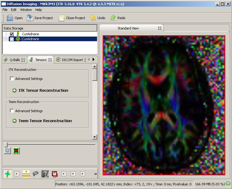
Tensor image after reconstruction
The q-ball reonstruction bundle implements a variety of reconstruction methods. The button "Average redundant gradients" accumulates the information that was acquired with multiple repetitions for one gradient. Vectors do not have to be precisely equal in order to be merged, if a "Merge radius" > 0 is configured.
The different reconstruction methods are described in the following:

The q-ball resonstruction view
Please recognize the tooltips in the advanced settings box. B0 threshold works the same as in tensor reconstruction. The maximum l-level configures the size of the spherical harmonics basis. Larger l-values (e.g. l=8) allow higher levels of detail, lower levels are more stable against noise (e.g. l=4). Lambda is a regularisation parameter. Set it to 0 for no regularisation. lambda = 0.006 has proven to be a stable choice under various settings. The multi lambda option lets you reconstruct different volumes with different lambdas with one click.
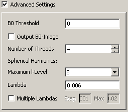
Advanced q-ball reconstruction settings
This is how a q-ball image should initially look after reconstruction. Standard q-balls feature a relatively low GFA and thus appear rather dark. Adjust the level-window to solve this.
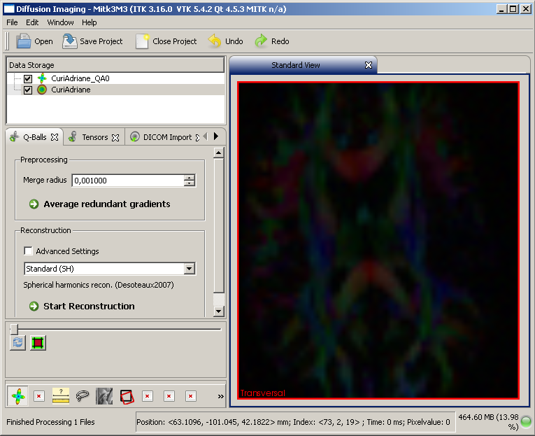
q-ball image after reconstruction
The dicom import does not cover all hardware manufacturers. In fact, it has only been thoroughly tested with Siemens dicom images. MITK-DI is also capable of reading the nrrd format, which is documented elsewhere [1, 2]. These files can be created by combining the raw image data with a corresponding textual header file. The file extension should be changed from *.nrrd to *.dwi or from *.nhdr to *.hdwi respectively in order to let MITK-DI recognize the diffusion related header information provided in the files.
In case your dicom images are readable by MITK-DI, select one or more input dicom folders and click import.
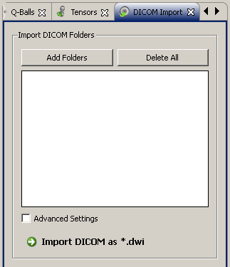
Dicom import
The advanced settings control some import options. "Use series details" and "Consider acquisition number" tell the algorithms, if series related information in the dicom header should be used to tell appart different image volumes. "Recursive" digs into the selected folders recursively. "Avg. dupl. grad." does the same as the corresponding "Average redundant gradients" in the q-ball reconstruction view (refer to the corresponding help section for details).
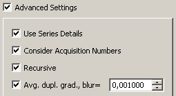
Advanced settings for dicom import
The quantification view allows the derivation of different scalar anisotropy measures for the reconstructed tensors (FA and RA) or q-balls (GFA).

Anisotropy quantification
In this small view, the visualization of ODFs and diffusion images can be configured. Depending on the selected image in the data storage, different options are shown here.
For a tensor or q-ball image, the third button from the left is of importance - it toggles the visibility of the glyphs. The spin box to its right lets you configer the number of glyphs that should maximaly be displayed. This is usefull to keep the system response time during rendering feasible. The other options configure normalization and scaling of the glyphs.
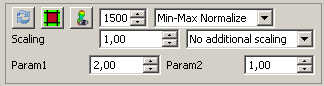
Configuring the ODF glyph visualization
In diffusion images, a slider lets you choose the desired image channel from the vector of images (each gradient direction one image) for rendering. Furthermore reinit can be performed and texture interpolation toggled.
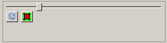
Configuring the diffusion imaging visualization
This is how a visualization with activated glyphs should look like:
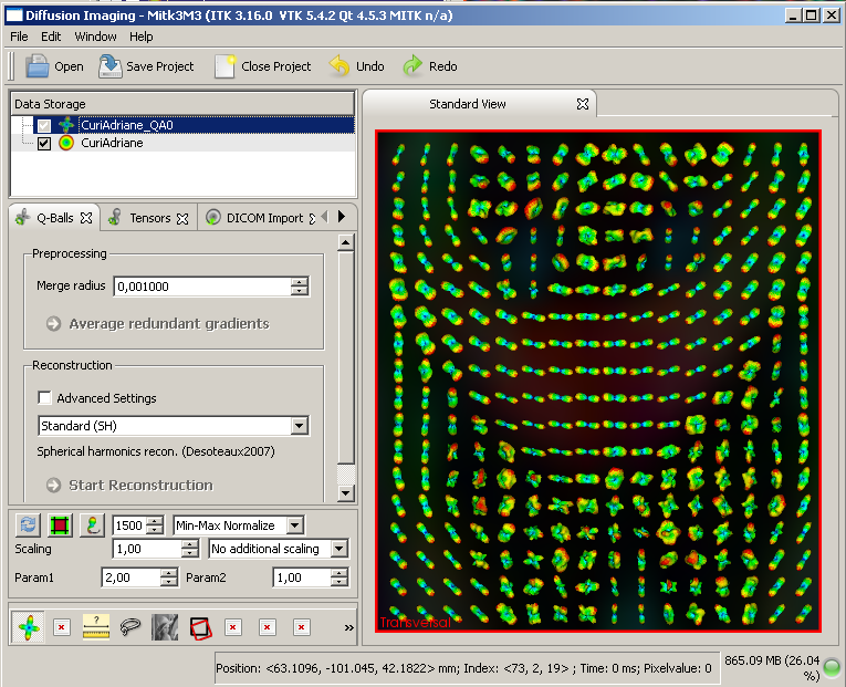
Q-ball image with ODF glyph visibility toggled ON
1. http://teem.sourceforge.net/nrrd/format.html
2. http://www.cmake.org/Wiki/Getting_Started_with_the_NRRD_Format
3. C.F.Westin, S.E.Maier, H.Mamata, A.Nabavi, F.A.Jolesz, R.Kikinis, "Processing and visualization for Diffusion tensor MRI", Medical image Analysis, 2002, pp 93-108
5. Tuch, D.S., 2004. Q-ball imaging. Magn Reson Med 52, 1358-1372.
6. Descoteaux, M., Angelino, E., Fitzgibbons, S., Deriche, R., 2007. Regularized, fast, and robust analytical Q-ball imaging. Magn Reson Med 58, 497-510.
7. Aganj, I., Lenglet, C., Sapiro, G., 2009. ODF reconstruction in q-ball imaging with solid angle consideration. Proceedings of the Sixth IEEE International Symposium on Biomedical Imaging Boston, MA.
8. Goh, A., Lenglet, C., Thompson, P.M., Vidal, R., 2009. Estimating Orientation Distribution Functions with Probability Density Constraints and Spatial Regularity. Med Image Comput Comput Assist Interv Int Conf Med Image Comput Comput Assist Interv LNCS 5761, 877 ff.
 1.7.2
1.7.2

