Difference between revisions of "Screenshots"
(username removed) |
|||
| (45 intermediate revisions by 6 users not shown) | |||
| Line 1: | Line 1: | ||
__NOTOC__ | __NOTOC__ | ||
| − | = | + | === Available Applications === |
| + | The applications shown in these screenshots are part of the open-source version of MITK. They are provided as plug-ins for the MITK application. You can test them by activating them in cmake, compiling and then starting the MITK workbench. | ||
| − | + | '''Many more examples can be found on the [[Projects|projects page]]!''' | |
| − | |||
| − | |||
| − | + | [[File:Screenshots$mitkisosurface.png|thumb|200px]] | |
| + | === Basic Image Processing === | ||
| + | This module provides an easy interface to fundamental image preprocessing and enhancement filters. It offers filter operations on 3D and 4D images in the areas of noise suppression, morphological operations, edge detection and image arithmetics, as well as image inversion and downsampling. | ||
| + | |||
| + | Please see [http://docs.mitk.org/nightly/org.basicimageprocessing.html#QmitkBasicImageProcessingUserManualDetails doxygen generated documentation] for more information on usage and supported filters. If you encounter problems using the module, please have a look at the [http://docs.mitk.org/nightly/org.basicimageprocessing.html#QmitkBasicImageProcessingUserManualTrouble Troubleshooting] page. | ||
| + | |||
----- | ----- | ||
| − | |||
| + | [[File:Screenshots$IGTTracking.jpg|thumb|200px]] | ||
| + | === IGT Tracking === | ||
| + | The IGT Tracking plug-in allows you to connect to a tracking device, track and visualize navigation tools and write the tracked data into a log file. Currently the devices Polaris, Aurora (both Northern Digital Inc. (NDI); Waterloo, Ontario, Canada) and Microntracker (Claron Technology, Inc.; Toronto, Ontario, Canada) are supported. The logging feature supports logging in XML or CSV format. Furthermore the plug-in allows for creating and editing navigation tool storages. These storages contain navigation tools of a tracking device, can be saved permanently and used later for any IGT application. The navigation data player, which is also included in this plug-in, plays recorded or artificial navigation data of one ore more tracking tools and visualizes their trajectory. | ||
| + | |||
| + | |||
| + | ----- | ||
| + | |||
| + | |||
| + | [[File:Screenshots$mitkisosurface.png|thumb|200px]] | ||
| + | === Iso Surface === | ||
| + | IsoSurface is a program module for creating surfaces (e.g. polygon structures) out of images. The user defines a threshold that seperates object and background inside the image. Pixels that belong to the object need grey values below the threshold. Pixles with grey values above the threshold will be ignored. The result is a polygon object that can be saved as an *.stl-object. | ||
| + | |||
| + | Please see [http://docs.mitk.org/nightly/org.isosurface.html doxygen generated documentation] for more information on usage. | ||
| + | |||
| + | |||
| + | ----- | ||
| + | |||
| + | |||
| + | [[File:Screenshots$slice_based_segmentation.png|thumb|200px]] | ||
| + | === Slice Based Segmentation === | ||
| + | A tool for manual segmentation of 3D images. You can draw binary images (segmentations) using a couple of simple tools, which all work on 2D slices of the original image (and have full undo support). A simple interpolation of missing slices is offered, as well as volume calculation and surface creation by marching cubes. [[Interactive_segmentation|More details]]. | ||
| + | |||
| + | |||
| + | ----- | ||
| + | |||
| + | |||
| + | [[File:Screenshots$THUMB_rigid_registration.png|thumb|200px]] | ||
| + | === Rigid Registration === | ||
The rigid registration tool gives an interface for performing different kinds of automatic 2D-2D and 3D-3D matching algorithms. The application lets the user load and select different volumes for registration. An overlay of the images are shown in the windows. To make the differences between the images more clearly, the color of the datasets can be set to red and green instead of both in grey values. The geometry of the moving image is updated for every iteration step during registration process and shown in the windows. The resulting transformed image can be saved. The set of parameters which were specified for registration can be saved as a preset for later use and loaded again. | The rigid registration tool gives an interface for performing different kinds of automatic 2D-2D and 3D-3D matching algorithms. The application lets the user load and select different volumes for registration. An overlay of the images are shown in the windows. To make the differences between the images more clearly, the color of the datasets can be set to red and green instead of both in grey values. The geometry of the moving image is updated for every iteration step during registration process and shown in the windows. The resulting transformed image can be saved. The set of parameters which were specified for registration can be saved as a preset for later use and loaded again. | ||
| + | |||
----- | ----- | ||
| − | |||
| + | [[File:Screenshots$PointBasedRegistrationFunctionality.png|thumb|200px]] | ||
| + | === Point Based Registration === | ||
The point based registration tool gives an interface for setting points in two datasets and perform a registration corresponding to these points. . The application lets the user load and select different datasets for registration. An overlay of the datasets are shown in the windows. To make the differences between the datasets more clearly, the color of the datasets can be set to red and green instead of both in grey values. The resulting transformed dataset can be saved. The set of points which were specified for a dataset can be saved for later use and loaded again. | The point based registration tool gives an interface for setting points in two datasets and perform a registration corresponding to these points. . The application lets the user load and select different datasets for registration. An overlay of the datasets are shown in the windows. To make the differences between the datasets more clearly, the color of the datasets can be set to red and green instead of both in grey values. The resulting transformed dataset can be saved. The set of points which were specified for a dataset can be saved for later use and loaded again. | ||
| + | |||
| + | |||
| + | ----- | ||
| + | |||
== More screenshots of possible applications == | == More screenshots of possible applications == | ||
| − | |||
These screenshots are made with MITK. However, the shown functionalities (program modules) are not part of the open source version that you can download. | These screenshots are made with MITK. However, the shown functionalities (program modules) are not part of the open source version that you can download. | ||
| + | [[File:Screenshots$interactive_fastmarching_level_set_tool.png|thumb|200px]] | ||
| − | |||
The application lets the user interactively delineate 3D data based on the Fast Marching Level Set Method. For the Level Set initialization seed points need to be defined (shown as crosses in the upper left window). During propagation of the segmentation the user gets feedback by previewing the intermediary results in the 2D orthogonal slices as well as a surface in the 3D window (bottom right). | The application lets the user interactively delineate 3D data based on the Fast Marching Level Set Method. For the Level Set initialization seed points need to be defined (shown as crosses in the upper left window). During propagation of the segmentation the user gets feedback by previewing the intermediary results in the 2D orthogonal slices as well as a surface in the 3D window (bottom right). | ||
| + | |||
----- | ----- | ||
| − | |||
| + | [[File:Screenshots$vesselTool.png|thumb|200px]] | ||
An application for the inspection of vessels by cutting planes orthogonal to their trajectories. In the MPR view, the origin of the plane is indicated by the colored lines. In the right view a surface reconstruction of the aorta is visualized in combination with the orthogonal plane (yellow). | An application for the inspection of vessels by cutting planes orthogonal to their trajectories. In the MPR view, the origin of the plane is indicated by the colored lines. In the right view a surface reconstruction of the aorta is visualized in combination with the orthogonal plane (yellow). | ||
Latest revision as of 16:35, 1 June 2016
Available Applications
The applications shown in these screenshots are part of the open-source version of MITK. They are provided as plug-ins for the MITK application. You can test them by activating them in cmake, compiling and then starting the MITK workbench.
Many more examples can be found on the projects page!
Basic Image Processing
This module provides an easy interface to fundamental image preprocessing and enhancement filters. It offers filter operations on 3D and 4D images in the areas of noise suppression, morphological operations, edge detection and image arithmetics, as well as image inversion and downsampling.
Please see doxygen generated documentation for more information on usage and supported filters. If you encounter problems using the module, please have a look at the Troubleshooting page.
IGT Tracking
The IGT Tracking plug-in allows you to connect to a tracking device, track and visualize navigation tools and write the tracked data into a log file. Currently the devices Polaris, Aurora (both Northern Digital Inc. (NDI); Waterloo, Ontario, Canada) and Microntracker (Claron Technology, Inc.; Toronto, Ontario, Canada) are supported. The logging feature supports logging in XML or CSV format. Furthermore the plug-in allows for creating and editing navigation tool storages. These storages contain navigation tools of a tracking device, can be saved permanently and used later for any IGT application. The navigation data player, which is also included in this plug-in, plays recorded or artificial navigation data of one ore more tracking tools and visualizes their trajectory.
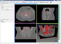
Iso Surface
IsoSurface is a program module for creating surfaces (e.g. polygon structures) out of images. The user defines a threshold that seperates object and background inside the image. Pixels that belong to the object need grey values below the threshold. Pixles with grey values above the threshold will be ignored. The result is a polygon object that can be saved as an *.stl-object.
Please see doxygen generated documentation for more information on usage.
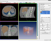
Slice Based Segmentation
A tool for manual segmentation of 3D images. You can draw binary images (segmentations) using a couple of simple tools, which all work on 2D slices of the original image (and have full undo support). A simple interpolation of missing slices is offered, as well as volume calculation and surface creation by marching cubes. More details.
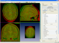
Rigid Registration
The rigid registration tool gives an interface for performing different kinds of automatic 2D-2D and 3D-3D matching algorithms. The application lets the user load and select different volumes for registration. An overlay of the images are shown in the windows. To make the differences between the images more clearly, the color of the datasets can be set to red and green instead of both in grey values. The geometry of the moving image is updated for every iteration step during registration process and shown in the windows. The resulting transformed image can be saved. The set of parameters which were specified for registration can be saved as a preset for later use and loaded again.
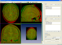
Point Based Registration
The point based registration tool gives an interface for setting points in two datasets and perform a registration corresponding to these points. . The application lets the user load and select different datasets for registration. An overlay of the datasets are shown in the windows. To make the differences between the datasets more clearly, the color of the datasets can be set to red and green instead of both in grey values. The resulting transformed dataset can be saved. The set of points which were specified for a dataset can be saved for later use and loaded again.
More screenshots of possible applications
These screenshots are made with MITK. However, the shown functionalities (program modules) are not part of the open source version that you can download.
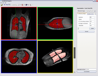
The application lets the user interactively delineate 3D data based on the Fast Marching Level Set Method. For the Level Set initialization seed points need to be defined (shown as crosses in the upper left window). During propagation of the segmentation the user gets feedback by previewing the intermediary results in the 2D orthogonal slices as well as a surface in the 3D window (bottom right).
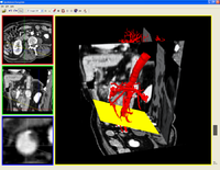
An application for the inspection of vessels by cutting planes orthogonal to their trajectories. In the MPR view, the origin of the plane is indicated by the colored lines. In the right view a surface reconstruction of the aorta is visualized in combination with the orthogonal plane (yellow).
